Part number
SKTTABE010
6.2mm Square (Surface Mount) SKTT Series
Automotive
MEMBERS ONLY
Basic information
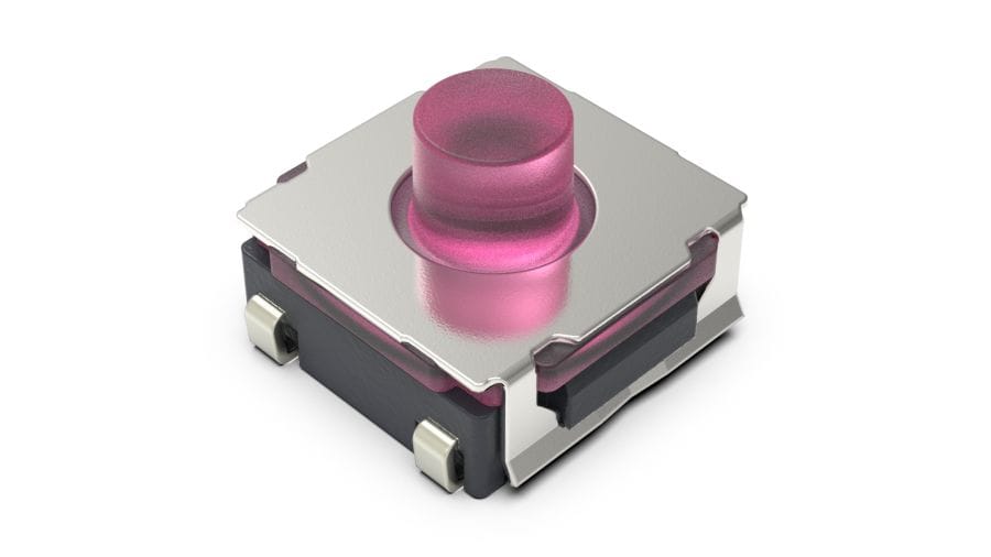
- Type
- Surface mount
- Operating force
- 4.0N
- Operating direction
- Top push
- Travel
- 0.36mm
- Product height
- 4.4mm
- Operating life
- 500,000 cycles
- Initial contact resistance
- 100mΩ max.
- Dimensions(W×D×H)
- 6.2×6.2×4.4
Specifications
- Series type
- Sharp feeling type
- Operating temperature range
- -40℃ to +90℃
- Absolute Maximum Ratings
- 50mA 16V DC
- Rating (min.)
- 10μA 1V DC
- Electrical performance
- Insulation resistance
- 100MΩ min. 100V DC for 1 min.
- Voltage proof
- 250V AC for 1 min.
- Durability
- Vibration
- 10 to 55 to 10Hz/min., the amplitude is 1.5mm for all the frequencies, in the 3 direction of X, Y and Z for 2 hours respectively
- Environmental performance
- Cold
- -40℃ 1,000h
- Dry heat
- 90℃ 1,000h
- Damp heat
- 60℃, 90 to 95%RH 1,000h
- Minimum order unit(pcs.)
- Japan
- 1,600
- Export
- 1,600


Land Dimensions

Viewed from switch mounting face
Circuit Diagram

Packing Specifications
Taping

- Number of packages (pcs.)
-
- 1 reel
- 1,600
- 1 case / Japan
- 12,800
- 1 case / export packing
- 12,800
- Reel width W(mm)
- 17.5
- Tape width (mm)
- 16
- Export package measurements (mm)
- 395×395×205
Soldering Conditions
Condition for Reflow
- Heating method
Double heating method with infrared heater. - Temperature measurement
Thermocouple 0.1 to 0.2 Φ CA(K) or CC(T) at solder joints (copper foil surface). A heat resisting tape should be used for fix measurement. - Temperature profile

(1) The above temperature shall be measured of the top of switch. There are cases where PC board’s temperature greatly differs from that of the switch, depending on the material, size, thickness of PC board’s and others. Care, should be taken to prevent the switch’s surface temperature from exceeding 260℃.
(2) Soldering conditions differ depending on reflow soldering machines. Prior verification of soldering condition is highly recommended.
- Allowable soldering time : 2 times Max.
Manual Soldering
- Soldering temperature
- 350℃ max.
- Duration of soldering
- 3s max.
- Capacity of soldering iron
- 60W max.
- Do not washing the TACT Switch™.
- Prevent flux penetration from the top side of the TACT switch™.
- Switch terminals and a PC board should not be coated with flux prior to soldering.
- The second soldering should be done after the switch returns to normal temperature.
Members-Only Content
SKTTABE010
MEMBERS ONLY
Product Drawing
Product Material List
F-S Curve
Notes are common to this series/models
- This site catalog shows only outline specifications. When using the products, please obtain formal specifications for supply.
- Please place purchase orders for taping products per minimum order unit (1 reel or a case).
Cautions
- When terminals are exposed to mechanical stress during soldering, it may cause degradation in deformation and electrical property.
- Through-hole PC board, or a PC board thickness other than the recommendation may cause larger heat stress. Prior verification is highly recommended.
- In prior to the 2nd soldering swith shall be stable with normal temperature. It may cause deformation of swith, loose terminals, terminal removed from PC board, and / or degradation of electric property.
- Verify samples with actual mass production conditions.
- After soldering, do not wash switches with a solvent, etc.
- The products are designed and manufactured for direct current resistance. Individual consultation is recommended for use of other resistances such as inductive (L) or capacitive (C).
- The sizes of holes and patterns on a PC board for mounting a switch, be asper the recommended dimensions in the product drawings.
- This switch is designed for manually operated units. Must not use this switch for a mechanical detection unit. For detection purposes, please use our detection switch.
- The switch will be broken if impact force or a greater stress than that specified is applied. Take great care not to let the switch be subject to greater stress than specified.
- Do not apply a force from the side of the stem.
- Be sure to push the center of switch for “without-stem” type. Extreme care is required for a hinge structure type, as the activation point may shift when it is pressed down.
- The circuit setting (software setting) shall be ensured for error-free operations, caused by bounce and chattering as specified by each model of the switches.
- Prior verification is needed to ensure that no corrosive gas-generating components are used near our switch. It may give negative influence such as contact failure.
- Contact resistance of a carbon contact type may vary depending on push force. Confirm that it functions sufficiently in using TACT Switch™ with a voltage divider circuit.
- Be aware of dust intrusion into a non dust-proof TACT switch™.
- Storage
- Store the products as delivered, at a normal temperature and humidity, without direct sunshine and corrosive gas ambient. Use them at an earliest possible timing, not later than six months upon receipt.
- After breaking the seal, keep the products in a plastic bag to prevent out ambient air, store them in the same environment as above, and use all as soon as possible.
- Do not stack too many switches.
- Store the key switches in released position.
- TACT Switch is a trademark or registered trademark of Alps Alpine Co., Ltd.