Part number
SSCM110100
Compact Two-way Detection Type SSCM Series
MEMBERS ONLY
Basic information


- Poles
- 1
- Positions
- 2
- Terminal type
- For PC board (Reflow)
- Operating force
- 0.35N max.
- Total travel position (mm)
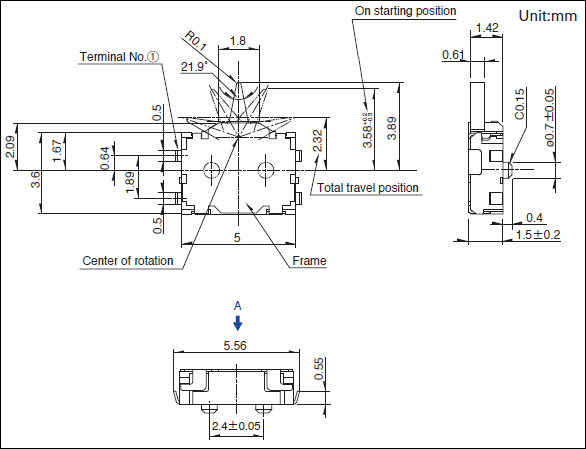
- 1.57
- Location lug
- With
- Dimensions (W×D×H)
- 4.0×5.0×1.5mm
Specifications
- Operating temperature range
- -10℃ to +60℃
- Rating(max.)/(min.)(Resistive load)
- 1mA 5V DC/50μA 3V DC
- Electrical performance
- Contact resistance(Initial/After operating life)
- 2Ω max./5Ω max.
- Insulation resistance
- 100MΩ min. 100V DC
- Voltage proof
- 100V AC for 1 minute
- Mechanical performance
- Terminal strength
- 0.5N for 1 minute
- Actuator strength
- 2N
- Durability
- Operating life without load
- 50,000 cycles 5Ω max.
- Operating life with load Rating(max.)(Resistive load)
- 50,000 cycles 5Ω max.
- Environmental performance
- Cold
- -20℃ 96h
- Dry heat
- 85℃ 96h
- Damp heat
- 40℃, 90 to 95%RH 96h
- Minimum order unit(pcs.)
- Japan
- 3,000
- Export
- 12,000
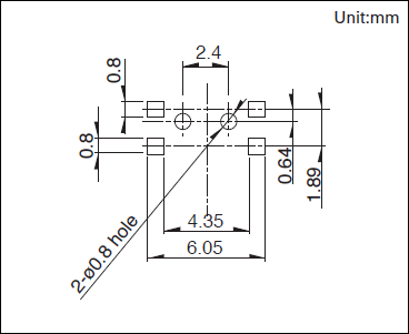
Land Dimensions
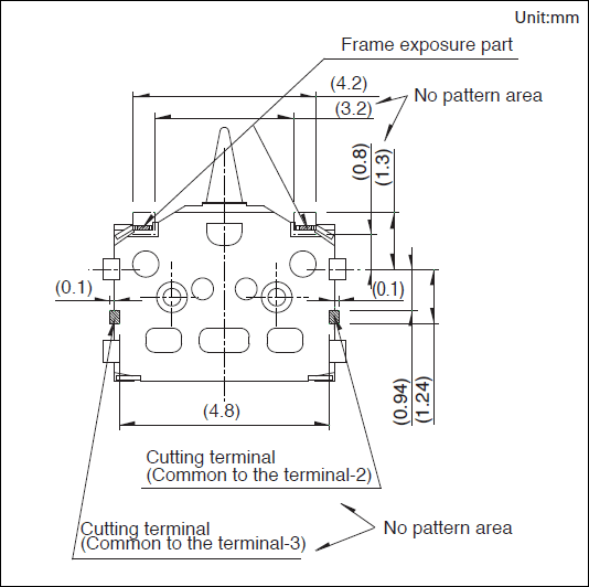
Viewed from direction A in the dimensions.
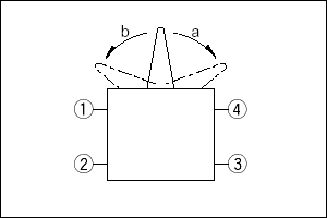
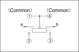
Terminal Layout
Circuit Diagram
Packing Specifications
Taping

- Number of packages (pcs.)
-
- 1 reel
- 3,000
- 1 case / Japan
- 6,000
- 1 case / export packing
- 12,000
- Tape width (mm)
- 16
- Export package measurements (mm)
- 417×409×139
Soldering Conditions
Example of Reflow Soldering Condition
- Heating method
Double heating method with infrared heater. - Temperature measurement
Thermocouple 0.1 to 0.2VCA(K)or CC(T)at soldering portion (copper foil surface). A heat resisting tape should be used for fixed measurement. - Temperature profile
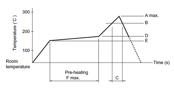
| A(℃) 3s max. |
B(℃) | C(s) | D(℃) | E(℃) | F(s) |
|---|---|---|---|---|---|
| 260 | 230 | 40 | 180 | 150 | 120 |
(1) The condition mentioned above is the temperature on the mounting surface of a PC board. There are cases where the PC board’s temperature greatly differs from that of the switch, surface depending on the PC board’s material, size, thickness, etc. The above-stated conditions shall also apply to switch surface temperatures.
(2) Soldering conditions differ depending on reflow soldering machines. Prior verification of soldering condition is highly recommended.
Reference for Hand Soldering
- Soldering temperature
- 350±5℃
- Soldering time
- 3s max.
Notes are common to this series/models
- This site catalog shows only outline specifications. When using the products, please obtain formal specifications for supply.
- Please place purchase orders per minimum order unit (integer).
Cautions
- Appling load to terminals during soldering under certain conditions may cause deformation and electrical property degradation.
- Avoid use of water-soluble soldering flux, since it may corrode the switches.
- Check and conform to soldering requirements under actual mass production conditions.
- No washing.
- The products are designed and manufactured for direct current resistance. Contact us for use of other resistances such as inductive (L) or capacitive (C).
- The circuit setting (software setting) shall be ensured for error-free operations, caused by bounce and chattering as specified by each model of the switches.
- Do not use the switches for a long time near the upper or lower limits of the specified operating temperatures. The use environments shall satisfy the specified range of the environmental tests in the specifications.
- In case of continuous operation near the upper and lower limits, see requirements of each model to check if possible.
- The switches designed specifically for automotive uses can be used for vehicles. No other switches shall be used for vehicles.
- Use the switches sufficiently distant (i.e. at a position closer to the full distance) from the ON Start Position.
- The switch-returning force cannot be used as a mechanical driving force of a set.
- Do not apply transverse force to the operating part while piling up PC boards in process and during transportation.
- Protect small and thin switches from external forces in the set mounting process.
- Use of a through-hole PC board, or a PC board of different thickness from the recommendation will have a different heat stress. Verify the soldering requirements thoroughly before use.
- Warped PC boards may change their properties. Carefully design and lay-out the patterns.
- Use of thinner PC boards will require extra care, since the switches may be floated.
- Use of the switches in a dusty environment may lead the dusts entering through the openings and cause imperfect contact or malfunction. Take this into account for set design.
- Corrosive gas if generated by peripheral parts of a set, malfunction such as imperfect contact may occur. Thorough investigation shall be required beforehand.
- Storage
Store the products as delivered at normal temperature and humidity, out of direct sunlight and away from corrosive gases. Use them as soon as possible and no later than six months after delivery.
Once the seal is broken, use them as soon as possible.
Measurement and Test Methods
- Rotational Torque (Operating Force)
- Measures the torque (operating force) necessary to rotate (move) the shaft (lever). Unless otherwise specified, measurement shall be made at ambient temperatures of 5 to 35°C, the shaft rotational speed shall be 60° per second, and the lever traveling speed shall be 20mm per second.
- Shaft Wobble
- Measures the amount of deflection at the specified position from the reference plane, with the specifiedbending moment, applied perpendicularly to the shaft from directions 180 degrees with respect to each other.
- Withstand Voltage
- Applies AC voltage to the specified spot for a minute and then checks for arc, burning, dielectric breakdown and other abnormalities. Respective terminals may be tested as a group. The sections described below shall be tested unless otherwise specified. However, if the section concerned is so constructed as to conduct, that particular part shall not be tested.
- Insulation Resistance
- Applies specified voltage to the specified locations and then measures the insulation resistance with a megger. The locations described below shall be tested unless otherwise specified. However, if the section concerned is so constructed as to conduct, that particular part shall not be tested.
- Sections to be Tested for Withstand Voltage and Insulation Resistance
-
- Between terminal and shaft (lever).
- Between terminal and metal cover (frame).
- Shaft (Lever) Strength against Push/Pull Actions
- Applies a specified force in the axial direction of the shaft (lever) for 19 seconds and then checks the operating part and other sections for deformation, breakage, operating conditions, etc.
