Part number
EC12E2430803
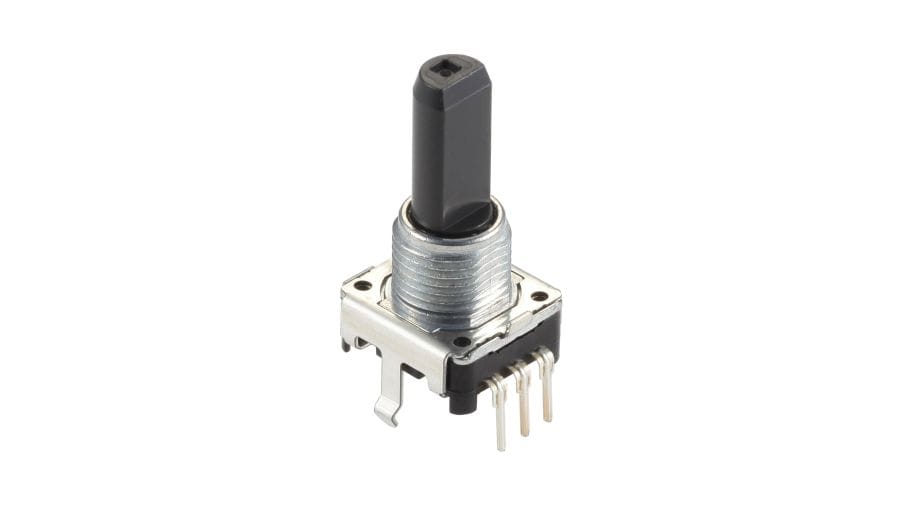
12mm Size Insulated Shaft Type EC12E Series
Basic information
- Actuator length
- 25.0mm
- Torque
-
Standard
25±15mN・m - Number of detent
- Without
- Number of pulse
- 24
- Control part orientation
- Vertical
- Dimensions
- 12mm size
Specifications
- Operating temperature range
- -10℃ to +70℃
- Electrical performance
- Ratings
- 0.5mA 5V DC
- Output signal
- Two phase A and B
- Max./min. operating current (Resistive load)
- 5mA/0.5mA
- Insulation resistance
- 10MΩ min. 50V DC
- Voltage proof
- 50V AC for 1 minute
- Mechanical performance
- Rotational torque
- 25±15mN·m
- Push-pull strength
- 80N
- Durability
- Operating life
- 15,000 cycles
- Minimum order unit(pcs.)
- Japan
- 1,900
- Export
- 1,900

Mounting Hole Dimensions

Viewed from mounting face.
Output Wave

Sliding Noise

V1=V2=1.5V max.
At R=10kΩ Chattering: 3ms max. Bounce: 2ms max.

Packing Specifications
Tray
- Number of packages (pcs.)
-
- 1 case / Japan
- 1,900
- 1 case / export packing
- 1,900
- Export package measurements (mm)
- 525×369×204
Soldering Conditions
Reference for Dip Soldering
- Preheating
-
- Soldering surface temperature
- 100℃ max.
- Heating time
- 1 min. max.
- Dip soldering
-
- Soldering temperature
- 260±5℃
- Soldering time
- 3±1s
- No. of solders
- 2 time max.
Reference for Hand Soldering
- Tip temperature
- 350℃ max.
- Soldering time
- 3s max.
- No. of solders
- 1 time
Notes are common to this series/models
- This site catalog shows only outline specifications. When using the products, please obtain formal specifications for supply.
- Please place purchase orders per minimum order unit (integer).
- Products other than those listed in the above chart are also available. Please contact us for details.
- Nuts and washers are not included. If required, please contact us.
Cautions
- Pulse count process
- With respect to pulse count design of encoders, operational speed, sampling time, and masking time, etc. should be taken into consideration. Be sure to confirm these factors before using the encoder. For your pulse count design, consider adding C/R filters on your circuit as shown below.

- Output Specifications
- Depending on the product, output at encoder detent positions can be specified either for both signals A and B, or for signal A only. Specifications vary according to the number of detents and other factors.

- Dew Condensation
- Do not use this product where dew or water drops might occur on the pattern surface of the encoder, etc. Insulation deterioration or shorting may occur.
- Usage Environment
- Use of the encoders in a dusty environment may lead the dusts entering through the openings and cause imperfect contact or malfunction. Take this into account for set design. Corrosive gas if generated by peripheral parts of a set, malfunction such as imperfect contact may occur. Thorough investigation shall be required before hand.
- Operation
- The encoders will be break if you apply a greater stress than that specified. Take great care not to let the encoders be subject to greater stress than specified.
- Looseness of the Shaft
- When long shafts are being employed, the looseness (deviation) tends to grow in proportion to the shaft length. Checking shaft looseness under actual operational conditions is recommended.
- Installation
- Insert these encoders to the specified mounting surface and mount them horizontally. If not mounted horizontally, these encoders will malfunction. Tighten the mounting screws by applying the specified torque. Tightening with larger torque than the specified one will result in malfunction or breakage of screws. Protect small and thin encoders from external forces in the set mounting process.
- Soldering
-
- To avoid potential contact issues, please do not solder wires to the top surface of the printed circuit board as shown in the diagram.
Solder all metal lugs into a substrate before use.

- Appling load to terminals during soldering under certain conditions may cause deformation and electrical property degradation.
- Avoid use of water-soluble soldering flux, since it may corrode the switches.
- Check and conform to soldering requirements under actual mass production conditions.
- When soldering twice, wait until the first soldered portion cools to normal temperature. Continuous heating will deform the external portions, loosen or dislodge terminals, or may deteriorate their electrical characteristics.
- Flux from around and above the PC board should not adhere to the switches.
- After mounting the switches, if you intend to put the board into an oven in order to harden adhesive for other parts, please consult with Alps Alpine.
- If you use a through-hole PC board or a PC board thinner or thicker than the recommendation, here may be greater heat stress. Verify the soldering conditions thoroughly before use.
- Solder the switches with detent at the detent position. Soldering switches fixed at the center of the detent may deform the detent mechanisms.
- No washing.
- To avoid potential contact issues, please do not solder wires to the top surface of the printed circuit board as shown in the diagram.
- Use of Chemicals
- Since synthetic resins such as polycarbonate are being used as the material for the insulated type shafts, avoid using this product under gassy environments containing such chemicals as ammonia, amines, alkaline water solutions, aromatic hydrocarbons, ketones, esters and halogenated hydrocarbons, especially under intensive gas environments.
- Operation at Low Temperature
- When these products are expected to be used under low temperature environments such as applications for car radios and car stereos, we can customize them for easier and more smooth rotary movements. When placing orders, indicate whether the low temperature specification is necessary or not.
- Storage
-
- Store the products as delivered, at a normal temperature and humidity, without direct sunshine and corrosive gas ambient. Use them at an earliest possible timing, not later than six months upon receipt.
- After breaking the seal, keep the products in a plastic bag to shut out ambient air, store them in the same environment as above, and use them up as soon as possible.
- Do not stack too many switches.
Measurement and Test Methods
- Rotational Torque (Operating Force)
- Measures the torque (operating force) necessary to rotate (move) the shaft (lever). Unless otherwise specified, measurement shall be made at ambient temperatures of 5 to 35°C, the shaft rotational speed shall be 60° per second, and the lever traveling speed shall be 20mm per second.
- Shaft Wobble
- Measures the amount of deflection at the specified position from the reference plane, with the specifiedbending moment, applied perpendicularly to the shaft from directions 180 degrees with respect to each other.
- Withstand Voltage
- Applies AC voltage to the specified spot for a minute and then checks for arc, burning, dielectric breakdown and other abnormalities. Respective terminals may be tested as a group. The sections described below shall be tested unless otherwise specified. However, if the section concerned is so constructed as to conduct, that particular part shall not be tested.
- Insulation Resistance
- Applies specified voltage to the specified locations and then measures the insulation resistance with a megger. The locations described below shall be tested unless otherwise specified. However, if the section concerned is so constructed as to conduct, that particular part shall not be tested.
- Sections to be Tested for Withstand Voltage and Insulation Resistance
-
- Between terminal and shaft (lever).
- Between terminal and metal cover (frame).
- Shaft (Lever) Strength against Push/Pull Actions
- Applies a specified force in the axial direction of the shaft (lever) for 19 seconds and then checks the operating part and other sections for deformation, breakage, operating conditions, etc.