Product FAQ
Sensors
- Magnetic Sensors
- Humidity Sensors
- Pressure Sensors
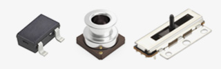
- Resistive Position Sensors
The output of the resistive position sensors is to compare the divided voltage. A resistive position sensor applies voltage to 1-3 terminals, and then sense the voltage in the 1-2 terminals. The output is the comparison of applying voltage to 1-3 terminals and output voltage of 1-2 terminals.
The resistance value representing a standard value for a resistor including resistive position sensors (a standard resistance value.)
Basic performance parameters of a potentiometer, including resistive position sensors that indicate the value and permissible range of the resistance between terminals 1 and 3.

・Rated power is the maximum electric power that can be applied continuously to a potentiometer.
・Maximum operating voltage is the maximum voltage that can be applied to the resistive element specified for the
potentiometer.
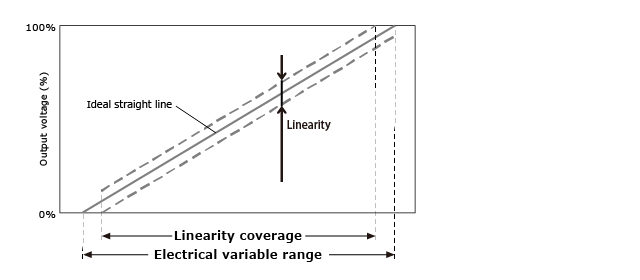
Value that shows the relationship of the mechanical travel distance and the output voltage in a deviation to a reference straight line (ideal straight line)
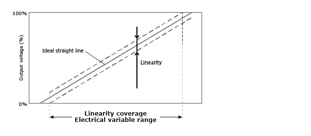
The electrical variable range indicates the variable range of output. However, the linearity coverage indicates the values within the electrical variable range. Both the electrical variable range and the linearity coverage are provided on each product.
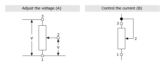
We recommend using resistive position sensors to adjust the voltage (Fig. A). Please do not use a resistive position sensor to control the current (Fig. B), because the set circuit might affect the contact resistance between resistive element and wiper.
・Hand (manual) soldering
Soldering is performed manually using a soldering iron.
・Dip soldering
Soldering is performed by passing the workpiece through flowing molten solder.
・Reflow soldering
This is a soldering method for surface mounting of components that uses solder paste or cream instead of molten
solder and involves heating the entire PC board and its components.