Part number
SRBE110301
Encoder and Push Operation Type SRBE Series
MEMBERS ONLY
Basic information
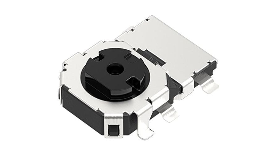
- Number of operating shafts
- Single-shaft
- Shaft material
- Resin
- Number of detent
- 12
- Number of pulse
- 6
- Operating direction
- Horizontal
- Mounting method
- Standard
- Travel (Push operation)
- 0.2mm
- Dimensions (W×D×H)
- 8.05×11×2.35mm
Specifications
- Operating temperature range
- -10℃ to +60℃
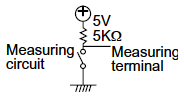
- Ratings (max.)/(min.) (Resistive load)
- 1mA 5V DC/50μA 3V DC
- Electrical performance
- Output voltage
-
1V max. at 1mA 5V DC (Resistive load)
- Insulation resistance
- 10MΩ min. 50V DC
- Voltage proof
- 50V AC for 1 minute
- Mechanical performance
- Push operating force
- 3.5±1.5N
- Encoders detent torque
- 3±2m N·m
- Actuator strength
- Push/pull directions
- 50N
- Durability
- Operating life
- Center push
- 100,000 cycles
- Encoder
- 100,000 cycles
- Operating life without load
- 100,000 cycles
- Environmental performance
- Cold
- -30℃ 96h
- Dry heat
- 85℃ 96h
- Damp heat
- 40℃, 90 to 95%RH 96h
- Minimum order unit(pcs.)
- Japan
- 1,500
- Export
- 6,000
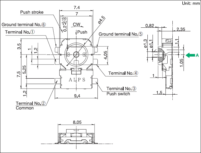
Land Dimensions
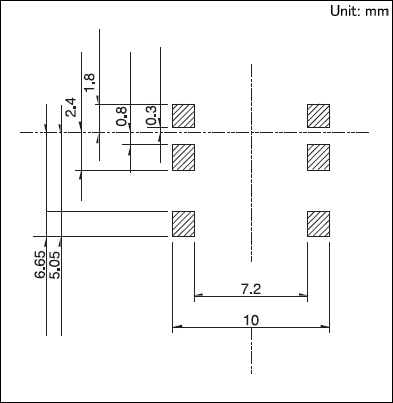
Viewed from direction A in the dimensions.
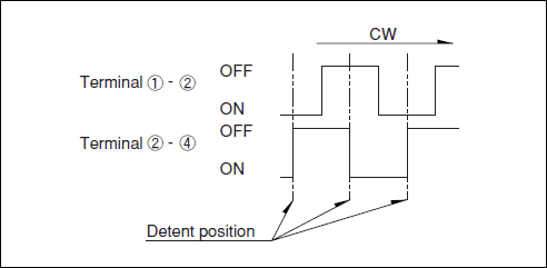
Output Signal
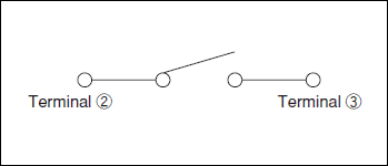
Circuit Diagram
Packing Specifications
Taping

- Number of packages (pcs.)
-
- 1 reel
- 1,500
- 1 case / Japan
- 3,000
- 1 case / export packing
- 6,000
- Tape width (mm)
- 24
- Export package measurements (mm)
- 428×413×172
Soldering Condition
Example of Reflow Soldering Condition
- Heating method:
Double heating method with infrared heater. - Temperature measurement:
Thermocouple 0.1 to 0.2 Φ CA (K) or CC (T) at solder joints (copper foil surface). A heat resisting tape should be used to fix thermocouple. - Temperature profile

| A | B | C | D | E | F | G | H | I | No. of reflows |
|---|---|---|---|---|---|---|---|---|---|
| 260℃ | 230℃ | 180℃ | 150℃ | 2 min. | - | - | 40s | - | 1 time |
(1) The condition mentioned above is the temperature on the mounting surface of a PC board. There are cases where the PC board’s temperature greatly differs from that of the switch, depending on the PC board’s material, size, thickness, etc. The above-stated conditions shall also apply to switch surface temperatures.
(2) Soldering conditions differ depending on reflow soldering machines. Prior verification of soldering condition is highly recommended.
Reference for Hand Soldering
- Tip temperature
- 350±5℃
- Soldering time
- 3s max.
- No. of solders
- 1 time
Notes are common to this series/models
- This site catalog shows only outline specifications. When using the products, please obtain formal specifications for supply.
- Please place purchase orders for taping products per minimum order unit (1 reel or a case).
Cautions
- Appling load to terminals during soldering under certain conditions may cause deformation and electrical property degradation.
- Avoid use of water-soluble soldering flux, since it may corrode the switches.
- Check and conform to soldering requirements under actual mass production conditions.
- In soldering twice, make sure the solder joints should go down to normal temperature. Continuing heating will cause deformation of switch, loose and fracfored terminals, or may deteriorate electrical characteristics.
- Flux from around and above the PC board should not adhere to the switches.
- For the sizes of holes and patterns on a PC board for mounting a switch, refer to the recommended dimensions in the outline drawings.
- This switch is designed for manually operated units. Must not use this switch for a mechanical detection unit. For detection purposes, please use our detection switches.
- After mounting the switches, if you intend to put the board into an oven in order to harden adhesive for other parts, please consult with ALPS.
- Use of a through-hole PC board, or a PC board of different thickness from the recommendation will have a different heat stress. Verify the soldering requirements thoroughly before use.
- Solder the switches with detent at the detent position. Soldering switches fixed at the center of the detent may deform the detent mechanisms.
- No washing.
- Protect small and thin switches from external forces in the set mounting process.
- Use of the switches with voltage below 1V DC or current below 10μA may make contacts unstable.
When using these switches in this way, please consult with us beforehand. - The products are designed and manufactured for direct current resistance. Contact us
for use of other resistances such as inductive (L) or capacitive (C). - The switch will be broken if impact force or a greater stress than that specified is applied. Take a great care not to let the switch be subject to greater stress than specified.
- Do not apply a force from the side of the stem.
- Be sure to push the center of switch for "without-stem"type. Extreme care is required for a hinge structure type because the stem press position moves when it is pressed.
- Insert these switches to the specified mounting surface and mount them horizontally. If not mounted horizontally, these switches will malfunction.
- Use of the switches in a dusty environment may lead the dusts entering through the openings and cause imperfect contact or malfunction. Take this into account for set design.
- Corrosive gas if generated by peripheral parts of a set, malfunction such as imperfect contact may occur. Thorough investigation shall be required beforehand.
- Be aware of dust intrusion into a non dust-proof-type TACT Switch™.
- Storage
- Store the products as delivered, at a normal temperature and humidity, without direct sunshine and corrosive gas ambient. Use them at an earliest possible timing, not later than six months upon receipt.
- Store the key switches with the switch in the released position.