Part number
SPPH120400
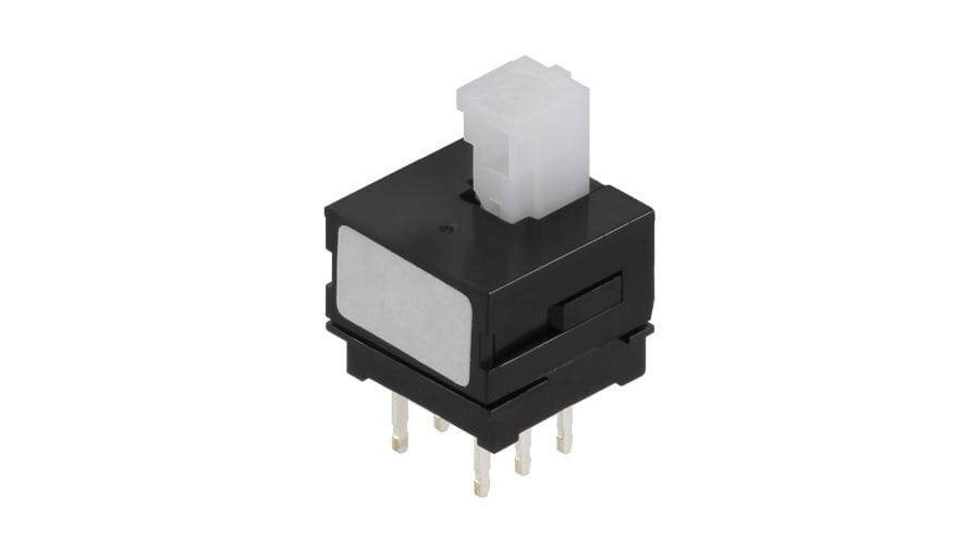
1.5mm-travel Vertical Type SPPH1 Series
Automotive
MEMBERS ONLY
Basic information
- Changeover timing
- Non shorting
- Travel
- 1.5mm
- Total travel
- 2.5mm
- Operating force
- 2(+1, -0.7)N
- Mounting method
- PC board
- Poles
- 2
- Knob style
- Short
- Operation
- Latching
- Terminal type
- Straight
- Dimensions (W×D×H)
- 10.0×10.0×8.5mm
Specifications
- Operating temperature range
- -10℃ to +60℃
- Rating (max.)/(min.) (Resistive load)
- 0.1A 30V DC/50μA 3V DC
- Electrical performance
- Contact resistance (Initial performance/After lifetime)
- 20mΩ max./40mΩ max.
- Insulation resistance
- 100MΩ min. 500V DC
- Voltage proof
- 500V AC for 1 minute
- Mechanical performance
- Terminal strength
- 5N for 1 minute
- Actuator strength
- Operating direction
- 50N
- Durability
- Operating life without load
- 10,000 cycles 40mΩ max.
- Operating life with load (at max. rated load)
- 10,000 cycles 40mΩ max.
- Environmental performance
- Cold
- -20℃ 96h
- Dry heat
- 85℃ 96h
- Damp heat
- 40℃, 90 to 95%RH 96h
- Minimum order unit(pcs.)
- Japan
- 800
- Export
- 4,000

Mounting Hole Dimensions

Viewed from direction A in the dimensions.
Terminal Configuration

Circuit Diagram

Packing Specifications
Bulk
- Number of packages (pcs.)
-
- 1 case / Japan
- 800
- 1 case / export packing
- 4,000
- Export package measurements (mm)
- 400×270×290
Soldering Conditions
Reference for Dip Soldering
- Items
-
- Preheating temperature
- -
- Preheating time
- -
- Dip soldering
-
- Soldering temperature
- 260±5℃
- Duration of immersion
- 10±1s
Reference for Hand Soldering
- Soldering temperature
- 350±10℃
- Soldering time
- 3+1/0s
Notes are common to this series/models
- This site catalog shows only outline specifications. When using the products, please obtain formal specifications for supply.
- Please place purchase orders per minimum order unit (integer).
- This products can be used in vehicles.
Although these products are designed to perform over a wide operating temperature range, please ensure that you receive and read the formal delivery specifications before use.
Cautions
- Appling load to terminals during soldering under certain conditions may cause deformation and electrical property degradation.
- Avoid use of water-soluble soldering flux, since it may corrode the switches.
- Check and conform to soldering requirements under actual mass production conditions.
- When soldering twice, wait until the first soldered portion cools to normal temperature. Continuous heating will deform the external portions, loosen or dislodge terminals, or may deteriorate their electrical characteristics.
- Flux from around and above the PC board should not adhere to the switches.
- After mounting the switches, if you intend to put the board into an oven in order to harden adhesive for other parts, please consult with us.
- Before soldering switches with locking mechanism, release the locks. If they are soldered without releasing the locks, the soldering heat may deform the locking mechanism.
- If you use a through-hole PC board or a PC board thinner or thicker than the recommendation, here may be greater heat stress. Verify the soldering conditions thoroughly before use.
- Solder the switches with detent at the detent position. Soldering switches fixed at the center of the detent may deform the detent mechanisms.
- No cleaning.
- Protect small and thin switches from external forces in the set mounting process.
- Tighten the mounting screws by applying the specified torque. Tightening with larger torque than the specified one will result in malfunction or breakage of screws.
- The products are designed and manufactured for direct current resistance. Contact us for use of other resistances such as inductive (L) or capacitive (C).
- The switch will be break if you apply a greater stress than that specified. Take great care not to let the switch be subject to greater stress than specified.
- Be sure to release the locks before removing the knobs. Otherwise, the locking mechanism may be deformed.
- Be sure to use the forced travel close to the position of the whole travel as mush as possible.
- Insert these switches to the specified mounting surface and mount them horizontally. If not mounted horizontally, these switches will malfunction.
- Use of the switches in a dusty environment may lead the dusts entering through the openings and cause imperfect contact or malfunction. Take this into account for set design.
- Corrosive gas if generated by peripheral parts of a set, malfunction such as imperfect contact may occur. Thorough investigation shall be required beforehand.
- Storage
Store the products as delivered at normal temperature and humidity, out of direct sunlight and away from corrosive gases. Use them as soon as possible and no later than six months after delivery.
Once the seal is broken, use them as soon as possible.
Measurement and Test Methods
- Rotational Torque (Operating Force)
- Measures the torque (operating force) necessary to rotate (move) the shaft (lever). Unless otherwise specified, measurement shall be made at ambient temperatures of 5 to 35°C, the shaft rotational speed shall be 60° per second, and the lever traveling speed shall be 20mm per second.
- Shaft Wobble
- Measures the amount of deflection at the specified position from the reference plane, with the specifiedbending moment, applied perpendicularly to the shaft from directions 180 degrees with respect to each other.
- Withstand Voltage
- Applies AC voltage to the specified spot for a minute and then checks for arc, burning, dielectric breakdown and other abnormalities. Respective terminals may be tested as a group. The sections described below shall be tested unless otherwise specified. However, if the section concerned is so constructed as to conduct, that particular part shall not be tested.
- Insulation Resistance
- Applies specified voltage to the specified locations and then measures the insulation resistance with a megger. The locations described below shall be tested unless otherwise specified. However, if the section concerned is so constructed as to conduct, that particular part shall not be tested.
- Sections to be Tested for Withstand Voltage and Insulation Resistance
-
- Between terminal and shaft (lever).
- Between terminal and metal cover (frame).
- Shaft (Lever) Strength against Push/Pull Actions
- Applies a specified force in the axial direction of the shaft (lever) for 19 seconds and then checks the operating part and other sections for deformation, breakage, operating conditions, etc.