Part number
SKHWAPA010
6.0mm Square Dust-proof (Snap-in) SKHW Series
Dust-proof Type
MEMBERS ONLY
Basic information
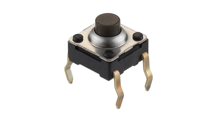
- Type
- Snap-in
- Operating force
- 1.57N
- Operating direction
- Top push
- Travel
- 0.3mm
- Operating life
- 1,000,000 cycles
- Initial contact resistance
- 100mΩ max.
- Stem color
- Dark gray
- Height
- 5.0mm
- Dimensions(W×D×H)
- 6.0×6.0×5.0mm
Specifications
- Series type
- Sharp feeling type
- Operating temperature range
- -40℃ to +90℃
- Rating (max.)
- 50mA 12V DC
- Rating (min.)
- 10μA 1V DC
- Electrical performance
- Insulation resistance
- 100MΩ min. 100V DC for 1 min.
- Voltage proof
- 250V AC for 1 min.
- Durability
- Vibration
- 10 to 55 to 10Hz/min., the amplitude is 1.5mm for all the frequencies, in the 3 direction of X, Y and Z for 2 hours respectivel
- Environmental performance
- Cold
- -40℃ 96h
- Dry heat
- 90℃ 96h
- Damp heat
- 60℃, 90 to 95%RH 96h
- Minimum order unit(pcs.)
- Japan
- 1,000
- Export
- 1,000

Mounting Hole Dimensions
Viewed from mounting face.
Circuit Diagram
Packing Specifications
Bulk
- Number of packages (pcs.)
-
- 1 case / Japan
- 10,000
- 1 case / export packing
- 30,000
- Export package measurements (mm)
- 309×476×347
Soldering Conditions
Conditions for Auto-dip
- Flux built-up
- Mounting surface should not be exposed to flux
- Preheating temperature
- Ambient temperature of the soldered surface of PC board.
100℃ max. - Preheating time
- 60s max.
- Soldering temperature
- 260℃ max.
- Duration of immersion
- 5s max.
- Number of soldering
- 2 times max.
Manual Soldering
- Soldering temperature
- 360℃ max.
- Duration of soldering
- 3s max.
- Capacity of soldering iron
- 60W max.
- Do not washing the TACT Switch™.
- Prevent flux penetration from the top side of the TACT switch™.
- Switch terminals and a PC board should not be coated with flux prior to soldering.
- The second soldering should be done after the switch returns to normal temperature.
- Use the flux with a specific gravity of at least 0.81.
(EC-19s-8 by TAMURA Corporation, or their equivalents.)
Members-Only Content
SKHWAPA010
MEMBERS ONLY
Product Drawing
Product Material List
F-S Curve
Notes are common to this series/models
- This site catalog shows only outline specifications. When using the products, please obtain formal specifications for supply.
- Please use 1.6mm thick PC boards.
- Please place purchase orders per minimum order unit (integer).
Cautions
- When terminals are exposed to mechanical stress during soldering, it may cause degradation in deformation and electrical property.
- Through-hole PC board, or a PC board thickness other than the recommendation may cause larger heat stress. Prior verification is highly recommended.
- In prior to the 2nd soldering swith shall be stable with normal temperature. It may cause deformation of swith, loose terminals, terminal removed from PC board, and / or degradation of electric property.
- Verify samples with actual mass production conditions.
- After soldering, do not wash switches with a solvent, etc.
- The products are designed and manufactured for direct current resistance. Individual consultation is recommended for use of other resistances such as inductive (L) or capacitive (C).
- The sizes of holes and patterns on a PC board for mounting a switch, be asper the recommended dimensions in the product drawings.
- This switch is designed for manually operated units. Must not use this switch for a mechanical detection unit. For detection purposes, please use our detection switch.
- The switch will be broken if impact force or a greater stress than that specified is applied. Take great care not to let the switch be subject to greater stress than specified.
- Do not apply a force from the side of the stem.
- Be sure to push the center of switch for “without-stem” type. Extreme care is required for a hinge structure type, as the activation point may shift when it is pressed down.
- The circuit setting (software setting) shall be ensured for error-free operations, caused by bounce and chattering as specified by each model of the switches.
- Prior verification is needed to ensure that no corrosive gas-generating components are used near our switch. It may give negative influence such as contact failure.
- Contact resistance of a carbon contact type may vary depending on push force. Confirm that it functions sufficiently in using TACT Switch™ with a voltage divider circuit.
- Be aware of dust intrusion into a non dust-proof TACT switch™.
- Storage
- Store the products as delivered, at a normal temperature and humidity, without direct sunshine and corrosive gas ambient. Use them at an earliest possible timing, not later than six months upon receipt.
- After breaking the seal, keep the products in a plastic bag to prevent out ambient air, store them in the same environment as above, and use all as soon as possible.
- Do not stack too many switches.
- Store the key switches in released position.
- TACT Switch is a trademark or registered trademark of Alps Alpine Co., Ltd.