Part number
RK097122T017
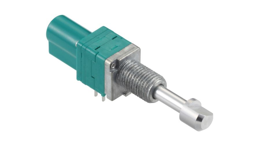
9mm Size Metal Shaft Multi-ganged Type RK097 Series
MEMBERS ONLY
Basic information
- Number of operating shafts
- Single-shaft
- Number of resistor elements
- Dual-unit
- Control part orientation
- Horizontal
- Fixing method of bushing
- Screw
- Shaft types
- Flat
- Length of the shaft
- 25mm
- Detent
- Without
- Total resistance
- 10kΩ
- Resistance taper
- 15A
- Dimensions
- 9mm Size
Specifications
- Operating temperature range
- -20℃ to +70℃
- Electrical performance
- Total resistance tolerance
- ±20%
- Rated power
- 0.05W
- Maximum operating voltage
- 50V AC, 10V DC
- Residual resistance
- 20Ω max.
- Gang error
- -40dB to 0dB 3dB max.
- Insulation resistance
- 100MΩ min. 250V DC
- Voltage proof
- 300V AC for 1 minute
- Mechanical performance
- Total rotational angle
- 300°(+10, -5)°
- Rotational torque
- 2 to 25mN·m
- Stopper strength
- 0.4N·m
- Push-pull strength
- 100N max.
- Vibration
- 10 to 55 to 10Hz/min., the amplitude is 1.5mm for all the frequencies, in the 3 direction of X, Y and Z and for 2 hours respectively
- Durability
- Operating life
- 15,000 cycles
- Specifications switches
- Switch type
- Without
- Attached mechanisms
- Attached mechanisms type
- Push-lock mechanism
- Shaft travel
-
Lock travel : 8±0.5mm
Total travel : 9±0.5mm
- Minimum order unit(pcs.)
- Japan
- 600
- Export
- 1,200
Mounting Hole Dimensions
Viewed from mounting side.
Example of Uses

Dimensions of Terminal

Dimensions of Bushings

Attached Parts

These parts are attached to the following products.
Packing Specifications
Tray
- Number of packages (pcs.)
-
- 1 case / Japan
- 600
- 1 case / export packing
- 1,200
- Export package measurements (mm)
- 540×373×225
Soldering Conditions
Reference for Dip Soldering
- Preheating
-
- Soldering surface temperature
- 100℃ max.
- Heating time
- 2 min. max.
- Dip soldering
-
- Soldering temperature
- 260±5℃ max.
- Soldering time
- 5±1s
- No. of solders
- 2 time max.
Reference for Hand Soldering
- Tip temperature
- 350℃ max.
- Soldering time
- 3s max.
- No. of solders
- 1 time
Notes are common to this series/models
- This site catalog shows only outline specifications. When using the products, please obtain formal specifications for supply.
- Please place purchase orders per minimum order unit (integer).
- This products can be used in vehicles.
- Products other than those listed in above products are also available. Please contact us for details.
Cautions
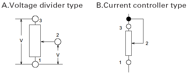
- Recommended Circuit Configuration
- Please use the potentiometer in the voltage adjustment circuit (Fig. A). Avoid using it in the current adjustment circuit (Fig. B) as it is affected by the contact resistance between the resistive element and the wiper.
- Direct Voltage
- When direct voltage is flown through this part, terminal to terminal insulation may deteriorate depending on the use environment. This is due to a migration phenomenon. Contact us if you are planning to use this part under direct voltage.
- Impedance on the Output Side
- There is a possibility that might de affected by contact resistance of resistive element and wiper in case of low impedance of output side in voltage regulation circuit. For this reason, we require that you adjust to impedance of output side more than 100 times of total resistance.
- Residual Resistance
- Although electric poles of resistors are generally formed by silver printing, we provide carbon coating over the silver poles to enhance reliability against sulfurization. Contact us if you wish to use the part in a low residual resistance state.
- Dew Condensation
- Avoid using the potentiometer where dew or water drops might occur on the surface of the resistor, etc. Deterioration of insulation or shorting may occur.
- Soldering
- To avoid potential contact issues, please do not solder wires to the top surface of the printed circuit board as shown in the diagram.
Solder all metal lugs into a substrate before use.

- Stress Being Applied to the Terminals
- Always pay special attention not to apply excessive stress when handling the terminals. Also, be sure to design appropriate soldering conditions.
- Looseness of the Shaft
- When lengthy shaft lengths are being employed, the looseness (deviation) tends to grow in proportion to the shaft length. Conducting a test under actual operating conditions is recommended.
- Chassis Mounting
- The use of a nut to fasten this part may lead to excessive tightening and can deteriorate the rotary contact performance, or strip the threads. Handle with care when tightening the nut.
- Use of Chemicals
- Since synthetic resins such as polycarbonate are being used as the material for the insulated type shafts, avoid using this part under gassy environments of such chemicals as ammonia, amines, alkali water solutions, aromatic hydrocarbons, ketones, esters and halogenated hydrocarbons, especially, under their intensive gas environments.
- Operation at Low Temperature
- When these products are expected to be used under low temperature environments such as applications for car radios and car stereos, we can customize them for easier and more smooth rotary movements. When placing orders, indicate whether the low temperature specification is necessary or not.
- Storage
-
- Store the products as delivered, at a normal temperature and humidity, without direct sunshine and corrosive gas ambient. Use them at an earliest possible timing, not later than six months upon receipt.
- After breaking the seal, keep the products in a plastic bag to shut out ambient air, store them in the same environment as above, and use them up as soon as possible.
- Do not stack too many switches.
The above operation notes are quoted from the
“Precaution and Guideline of Potentiometer for Electrical Devices”, which is a technical report issued by the Japan Electronics and Information Technology Industries Association RCR-2191A (in March 2002).
For details, see the above technical report.
Measurement and Test Methods
Electrical performance
- Total Resistance
- With the shaft (lever) placed at the termination of terminal 1 or 3, total resistance shall be determined by measuring the resistance between the resistor terminals 1 and 3 unless otherwise specified.
- Rated Power
- Rated power shall be the maximum value of electric power that can be applied continuously to the whole area of a resistor (between terminals 1 and 3) at the rated ambient temperature.
The rated ambient temperature of a carbon film resistor shall be 50°C. The maximum power at an ambient temperature of 50 to 70°C shall be obtained by multiplying the rated power by the rated power ratio determined from the derating curve shown below.

- Rated Voltage
- Rated voltage is associated with the rated power and shall be determined by the following equation. When the resulting rated voltage exceeds the maximum operating voltage of a specific resistor, the maximum operating voltage shall be taken as the rated voltage.
- Tap Resistance
- Determined by measuring the resistance between a tap terminal and a specified terminal (terminal 1 or terminal 3).
- Residual Resistance
- With the shaft (lever) placed at the termination of terminal 1, the resistance shall be measured between the terminals 1 and 2. Next, with the shaft (lever) placed at the end of terminal 3, the resistance shall be measured between the terminals 2 and 3. If there are tap terminals, the shaft (lever) shall be turned (moved) and the resulting minimum resistance between the tap terminal and the terminal 2 shall be measured.
- Maximum Attenuation Level
- With the shaft placed at the termination of terminal 1, maximum attenuation level shall be determined by measuring the voltage applied between the terminals 1 and 2, and calculating the ratio to the voltage applied between the terminals 1 and 3.
Unless otherwise specified, the value obtained shall be used in place of the residual resistance of a rotary potentiometer for volume control. - Insertion Loss
- With the shaft placed at the termination of terminal 3, insertion loss shall be determined by measuring the voltage applied between the terminals 1 and 2 and calculating the ratio to the voltage applied between the terminals 1 and 3.
Unless otherwise specified, the value obtained shall be used in place of the residual resistance of a rotary potentiometer for volume control. - Sliding Noise
- Measured by connecting the resistor to an amplifier having frequency characteristics specified in JIS C 6443, applying DC voltage of 20V between the terminals 1 and 3 (if rated voltage is 20V or less, this voltage shall be applied) and by rotating (moving) the shaft (lever) at a speed of about 30 cycles per minute.
- Voltage Withstand
- Determined by applying AC voltage to the specified locations for one minute to checking for any arc, burning, dielectric breakdown and other abnormalities. Respective terminals may be tested together. The locations described below shall be tested unless otherwise specified. However, if the section concerned is so constructed as to conduct, that particular part shall not be tested.
- Insulation Resistance
- Measured with a megger by applying specified voltage to the specified locations.
The locations below shall be tested unless otherwise specified. However, if the section concerned is so constructed as to conduct, that particular part shall not be tested. - Measuring Locations For Withstand Voltage and Insulation Resistance
-
- Between terminal and shaft (lever)
- Between terminal and metal cover (frame)
- Between terminals connected to separate resistor element and terminal connected to another resistor element (of multi-ganged-unit)
- Between switch terminal and shaft
- Between switch terminal and resistance terminal
- Between switch terminal and metal cover
- Gang Error
- With the shaft (lever) placed in the specified position, gang error shall be determined by applying test voltage of 2 to 15V (sine-wave RMS value) between the terminals 1 and 3 at 1,000±200Hz and measuring the voltage between the resistor terminal 2 and the specified terminal (terminal 1 or 3) and then by using the following equation.
If there are no questions on determination, DC voltage may be applied for this test.

Where,
V1: Voltage between the reference resistor terminals 1 and 2 (voltage between the terminals 2 and 3 if the resistance tapers are C, E and reverse D)
V2: Voltage between the non-reference resistor terminals 1 and 2 (voltage between the terminals 2 and 3 if the resistance tapers are C, E and reverse D)
If there is a tap terminal, measurement shall be made by connecting a fixed resistor whose resistance is equivalent to 1/10 of the nominal total resistance between the tap terminal and the terminal 1 (if the resistance taper is C, make connection between

- Contact Resistance of Switch
- Unless otherwise specified, contact resistance of switch shall be determined by measuring drop voltage when 5V DC, 1A is applied between contacts and the contacts are closed.
Mechanical Performance
- Total Rotational Angle (Travel)
- Determined by measuring the rotational angle (travel) when the shaft (lever) is turned (moved) from the termination position of terminal 1 to the termination position of terminal 3.
- Rotational Torque (Operating Force)
- Determined by measuring the torque (operating force) necessary to turn (move) the shaft (lever). Unless otherwise specified, measurement shall be made at an ambient temperature of 5 to 35°C, and the shaft rotational speed shall be 60° per second and the lever moving speed 20mm per second.
- Starting Torque (Starting Force)
- Determined by measuring a torque (operating force) necessary to turn (move) the shaft (lever) for the first time after allowing the test piece to stand for a long period of time. Unless otherwise specified, measurement shall be made at an ambient temperature of 5 to 35°C, and the shaft rotational speed shall be 60° per second and the lever moving speed 20mm per second.
Remarks:
To be specified only when required in particular. - Shaft Wobble
- Determined by measuring the amount of deflection at a position of 30mm from the reference surface with a bending moment of 0.1N·m (50mN·m for insulated shaft) applied perpendicularly to the shaft from 180° different directions at a point within 3mm from the place where a smooth cylindrical surface of the shaft ceases to exist. However, if the length of the shaft is less than 30mm, proportional calculation shall be used.
- Allowable Operating Torque for Shaft (Lever)
- With the shaft (lever) placed at the termination of terminal 1, a specified torsional moment (force) shall be applied in that direction for 10 seconds. Next, the shaft (lever) shall be placed at the termination of terminal 3 and a specified torsional moment (force) shall be applied similarly, to check the control part and other related sections for any deformation or breakage.
- Push-pull Strenght (Lever Push-pull Strenght)
- A specified force shall be applied in the axial direction of the shaft (lever) for 10 seconds to check the control part and other sections for any deformation or breakage and for operating condition.
Resistance Taper
- Resistance Taper
- With the shaft (lever) placed in the specified position, resistance taper shall be determined by measuring the voltage between the specified terminals (between terminals 1 and 2 or between terminals 2 and 3)and calculating the percentage in reference to the voltage between terminals 1 and 3.
Reference: Standard resistance tapers in reference to rotational angles (travels) are as shown below.
