Part number
RD7121008A
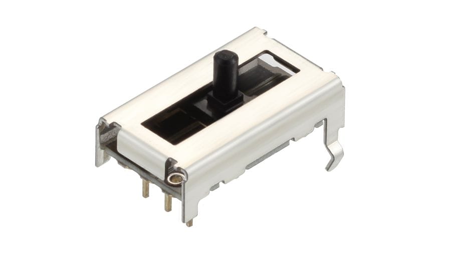
Linear Type (Exclusively Used to Detect the Angle of Vehicle Head Lights) RD7 Series
Automotive
MEMBERS ONLY
Basic information
- Travel
- 12mm
- Control part orientation
- Vertical
- Total resistance
- 10kΩ
- Linearity guarantee range
- 9mm
- Linearity
- ±1%
- Operating life
- 100,000 cycles
- Rated voltage
- 12V DC
- Length of lever
- 4.0mm
- Length of terminal
- 3.4mm
- Dimensions
- 10.0×18.0×5.0mm
Specifications
- Operating temperature range
- -40℃ to +105℃
- Mechanical performance
- Operating force
- 2N max.
- Electrical performance
- Total resistance tolerance
- ±20%
- Environmental test
- Cold
- -40℃ 96h
- Dry heat
- 105℃ 96h
- Damp heat
- 40℃, 90 to 95%RH 96h
- Minimum order unit(pcs.)
- Japan
- 1,800
- Export
- 3,600
Mounting Hole Dimensions
Viewed from mounting side
Do not wire the shaded area
Circuit Diagram
Packing Specifications
Tray
- Number of packages (pcs.)
-
- 1 case / Japan
- 1,800
- 1 case / export packing
- 3,600
- Export package measurements (mm)
- 507×363×216
Soldering Conditions
Reference for Dip Soldering
- Preheating
-
- Soldering surface temperature
- 100℃ max.
- Heating time
- 1 min. max.
- Dip soldering
-
- Soldering temperature
- 260℃ max.
- Soldering time
- 5s max.
- No. of solders
- 1 time
Reference for Hand Soldering
- Tip temperature
- 350℃ max.
- Soldering time
- 3s max.
Notes are common to this series/models
- This site catalog shows only outline specifications. When using the products, please obtain formal specifications for supply.
- For Linearity, various specifications will be available, depending on the applications. Please consult with us when lacing your orders.
- Please place purchase orders per minimum order unit (integer).
Cautions
- Use of Chemicals
- The sensors make use of synthetic resins, therefore avoid use in environments where there is a strong presence of gases from chemicals such as ammonia, amines, alkaline aqueous solutions, aromatic hydrocarbons, ketones, esters and halogenated hydrocarbons.
- Measures to Deal with Noise Problems
- While data is being received from the sensor, on rare occasions, penetrating external noise may cause interference with the outputs.
To minimize the probability of this phenomenon pay attention to the following when you program the relevant software
ex)- Receiving of data should always be repeated a number of times to ensure that you obtain a mean value.
- Have the system determine when/how to invalidate any data received in error.
- When doubt occurs let the system receive the subject data again and reconfirm that you have eliminated the anomaly.
- Soldering
- Avoid wiring and soldering that causes the solder to seep through to the top of the PC board (as illustrated). This can lead to a contact failure in the terminal section. If solder seepage is unavoidable, please consult with us.

- Connection Impedance
- Resistive position sensors are constructed in a way that contact resistance (R1 below) occurs within the sensor. To reduce the effect of contact resistance (R1), set the impedance within the circuit connected to the output terminal to greater than 1MΩ.

- Dew Condensation
- Avoid using the sensor where dew or water vapor might be caused to condense on the surface of the resistor - deterioration of insulation or shorting may occur.
- Storage
-
- Store the products as delivered, at a normal temperature and humidity, without direct sunshine and corrosive gas ambient. Use them at an earliest possible timing, not later than six months upon receipt.
- After breaking the seal, keep the products in a plastic bag to shut out ambient air, store them in the same environment as above, and use them up as soon as possible.
- Do not stack too many switches.
Measurement and Test Methods
Resistive Position Sensor
- Total Resistance
- Unless otherwise specified, total resistance is the resistance measured between resistor terminals 1 and 3.
- Rated Voltage
- The rated voltage corresponding to the rated power shall be determined by the following equation. When the resulting rated voltage exceeds the maximum operating voltage of a specific resistor, the maximum operating voltage shall be taken as the rated voltage.
