How to Prevent Detector Switch Failure – Pre-Use Checklist
Overcurrent
Overloading Causes 60% Percent of Faults
Voltage/current overloading occurs in switching transients
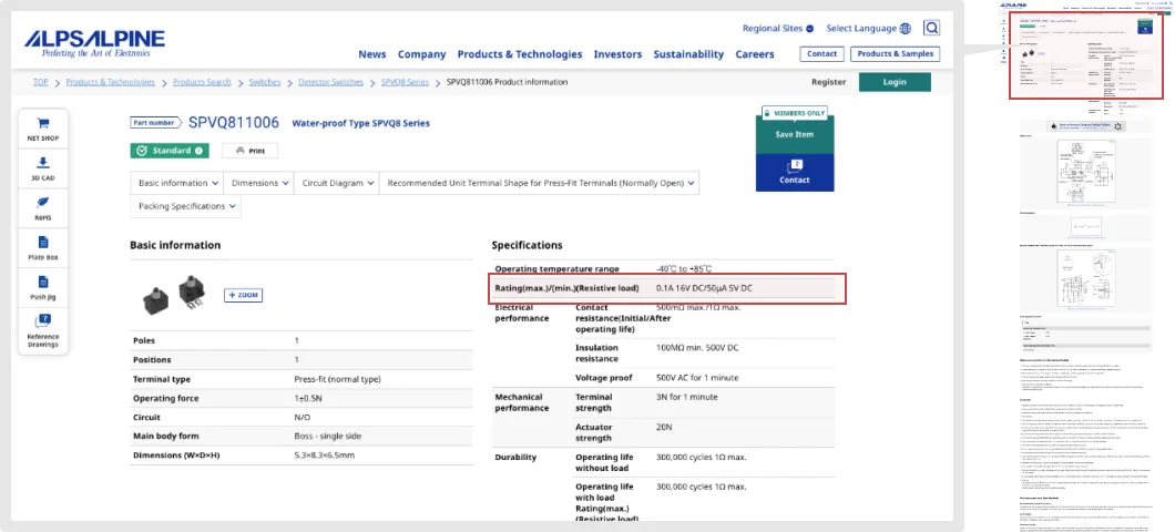
Alps Alpine detector switches are designed to achieve the "Rating (max.)/(min.)(resistive load)" specification.
Ratings may be exceeded due to inrush current, overcurrent or overvoltage occurring in transient states of on/off switching, causing failure.
If using a switch in other than a resistive load circuit, pay attention to the maximum and minimum ratings.
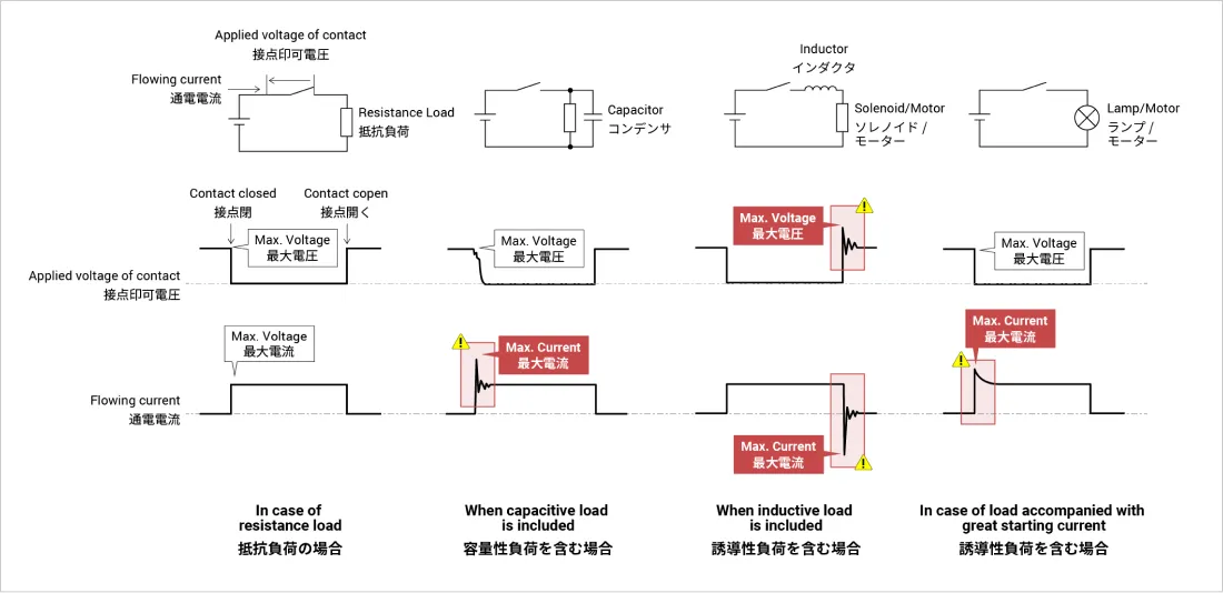
Here are some waveform examples.
In design, please use an oscilloscope to check on/off waveforms of detector switches.
Check that voltage and current fall within the rating range even over short durations like overshooting and undershooting.
Consider a Contact Protection Circuit
Even if a constant current is set within the power rating, sometimes an inrush current tens of times larger than the rated current can occur with a capacitive or inductive load, or a starting current load, exceeding the absolute maximum rating.
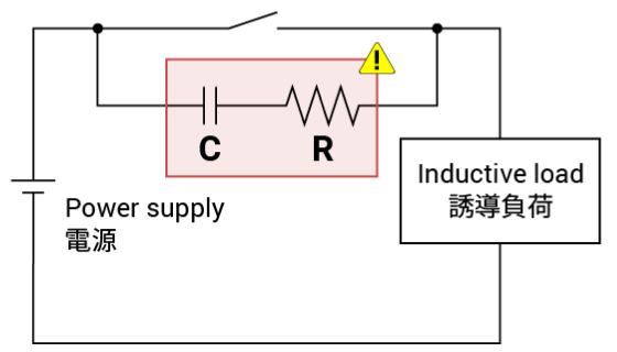
As a countermeasure, please consider adding a contact protection circuit.
Here are some examples.
| Protection circuit |
|
|---|---|
| Constants |
R: Several tens of ohms. C: 0.1µF. |
| Notes | Use when arc-breaking capability between contacts is a concern. |
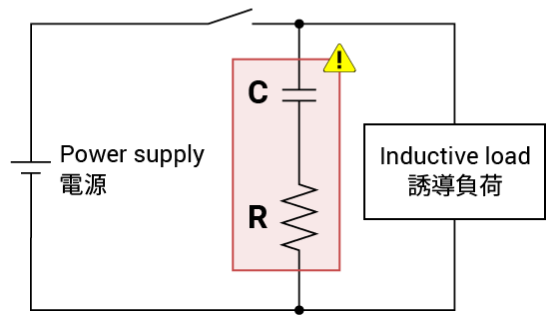
| Protection circuit |
|
|---|---|
| Constants |
R: Inductive load resistance value. C: 0.1µF. |
| Notes | This CR circuit is recommended as a protection circuit over the example above. |
| Protection circuit |
|
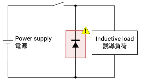
|---|---|
| Constants | Use a diode with a reverse breakdown voltage that is 10 times the circuit voltage and a forward current at least as large as the load current. |
| Notes | If the release time is too long, adding a Zener diode helps. |
| Protection circuit |
|
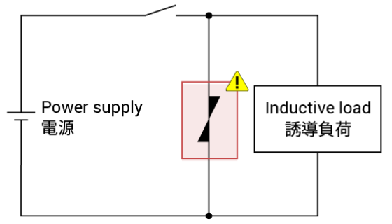
|---|---|
| Constants | The cutoff voltage of the varistor should be at least 1.5 times the supply voltage. The energy rating should be at least 1J. |
| Notes |
| Protection circuit |
|
|---|---|
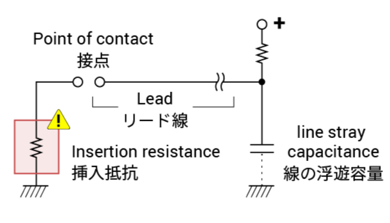
| Constants |
With long wiring, inrush current may occur due to stray capacitance. Insert a limiting resistor of 10-50Ω. |
| Notes | The same is required to cope with additional capacitance in ESD protection circuits. |
* Because adding a contact protection circuit extends the release time, you will want to pay attention to the operating time.

- Checking the Specifications
-