How to Prevent Detector Switch Failure – Pre-Use Checklist
Overloading Causes 60% Percent of Faults
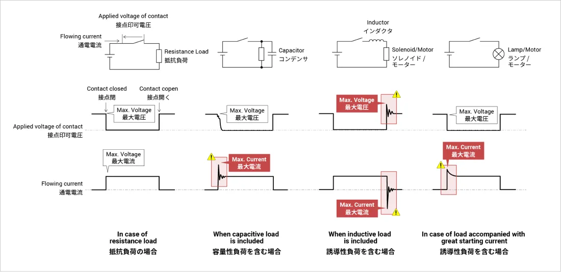
Voltage/current overloading occurs in switching transients
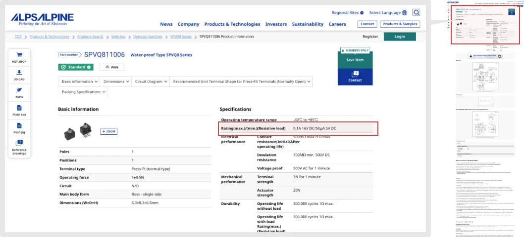
Alps Alpine detector switches are designed to achieve the "Rating (max.)/(min.)(resistive load)" specification.
Ratings may be exceeded due to inrush current, overcurrent or overvoltage occurring in transient states of on/off switching, causing failure.
If using a switch in other than a resistive load circuit, pay attention to the maximum and minimum ratings.
Here are some waveform examples.
In design, please use an oscilloscope to check on/off waveforms of detector switches.
Check that voltage and current fall within the rating range even over short durations like overshooting and undershooting.
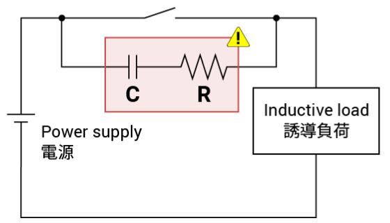
Consider a Contact Protection Circuit
Even if a constant current is set within the power rating, sometimes an inrush current tens of times larger than the rated current can occur with a capacitive or inductive load, or a starting current load, exceeding the absolute maximum rating.
As a countermeasure, please consider adding a contact protection circuit.
Here are some examples.
| Protection circuit |
|
|---|---|
| Constants |
R: Several tens of ohms. C: 0.1µF. |
| Notes | Use when arc-breaking capability between contacts is a concern. |
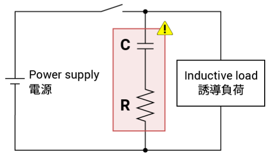
| Protection circuit |
|
|---|---|
| Constants |
R: Inductive load resistance value. C: 0.1µF. |
| Notes | This CR circuit is recommended as a protection circuit over the example above. |
| Protection circuit |
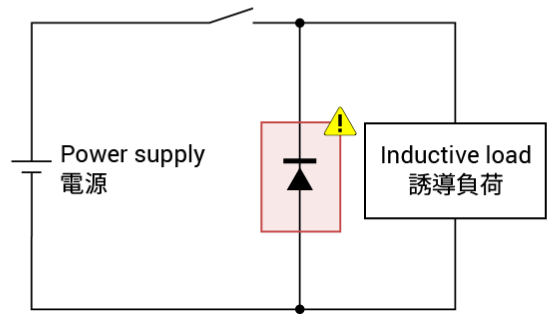
|
|---|---|
| Constants | Use a diode with a reverse breakdown voltage that is 10 times the circuit voltage and a forward current at least as large as the load current. |
| Notes | If the release time is too long, adding a Zener diode helps. |
| Protection circuit |
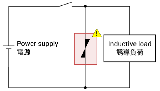
|
|---|---|
| Constants | The cutoff voltage of the varistor should be at least 1.5 times the supply voltage. The energy rating should be at least 1J. |
| Notes |
| Protection circuit |
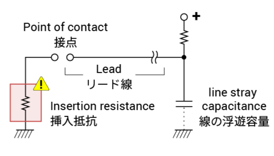
|
|---|---|
| Constants |
With long wiring, inrush current may occur due to stray capacitance. Insert a limiting resistor of 10-50Ω. |
| Notes | The same is required to cope with additional capacitance in ESD protection circuits. |
* Because adding a contact protection circuit extends the release time, you will want to pay attention to the operating time.

- Checking the Specifications
-
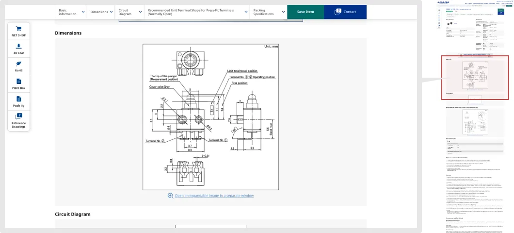
Avoid Operating Body Overpush
Excessive pushing can cause faults
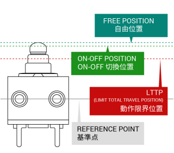
The diagram above shows the names of different positions in a detector switch.
We will refer to the diagram to explain considerations in push design.
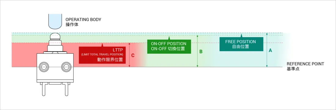
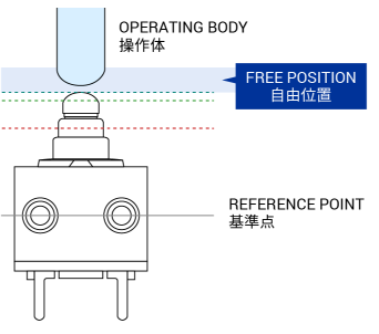
Free position:
Position the operating body at a distance further than A when the switch is off
If the switch is constantly pushed by the operating body, in a state of pre-tension, it may not accurately detect on and off.
To avoid switch pre-tension, set a free position at a distance further than the free position indicated by A.
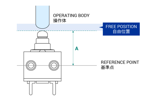
Determination of free position: Position at a distance further than A
* Make sure the switch has no pre-tension in free position.
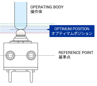
Full travel distance:
Position the operating body at the midway point between B and C when the switch is on
When the switch is on, the operating body needs to be positioned between the on-off switching position (B) and the limit total travel position (LTTP)(C).
Set the depressed position, when the switch is on, to a position within the red area in the diagram below.
(For convenience, here we will call it the optimum position)
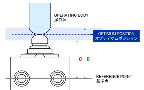
Determination of optimum position: Optimum position is between B and C. Use the midway point. (B+C)/2
Tolerances of B (on-off switching position) and C (LTTP) dimensions must also be taken into account.
A depressed position deeper than the LTTP (C) can cause faults.
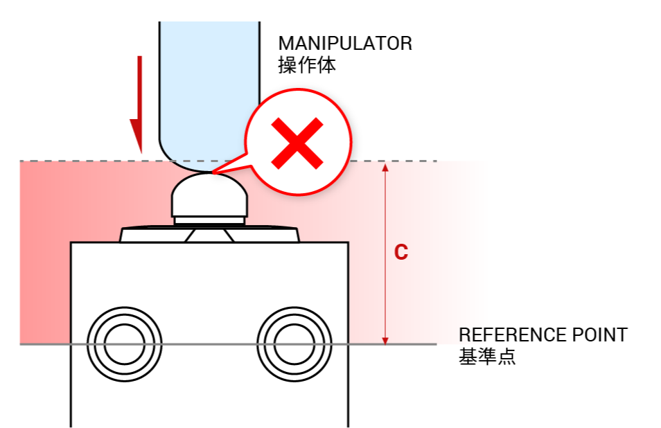
Set full travel to a distance further from the reference line than C.
Tolerance between detector switch and target equipment must be considered when determining an optimal design.
Example: SPVQ810102
ON-OFF POSITION: 7.1mm
LTTP(LIMIT TOTAL TRAVEL POSITION):5.4mm
Position at a distance further than 7.6mm
Caution: Detailed design should take into consideration tolerance of the detector switch, tolerance in installation, and tolerance of push distance.
(5.4+7.1)/2=6.15mm
- Checking the Specifications
-