How to Prevent Detector Switch Failure – Pre-Use Checklist
Overloading Causes 60% Percent of Faults
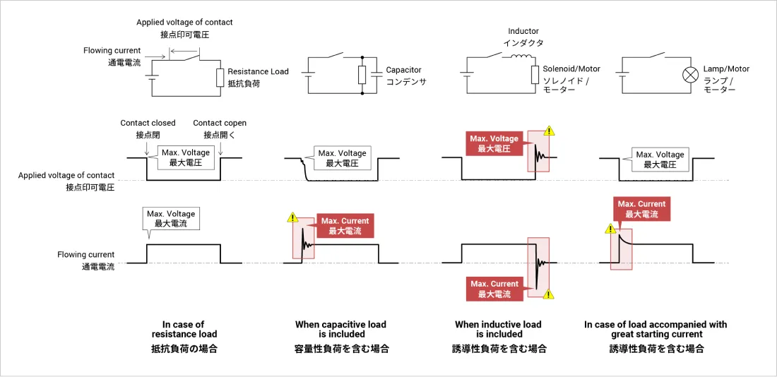
Voltage/current overloading occurs in switching transients
Alps Alpine detector switches are designed to achieve the "Rating (max.)/(min.)(resistive load)" specification.
Ratings may be exceeded due to inrush current, overcurrent or overvoltage occurring in transient states of on/off switching, causing failure.
If using a switch in other than a resistive load circuit, pay attention to the maximum and minimum ratings.
Here are some waveform examples.
In design, please use an oscilloscope to check on/off waveforms of detector switches.
Check that voltage and current fall within the rating range even over short durations like overshooting and undershooting.
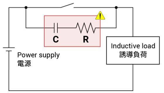
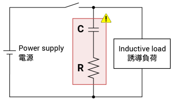
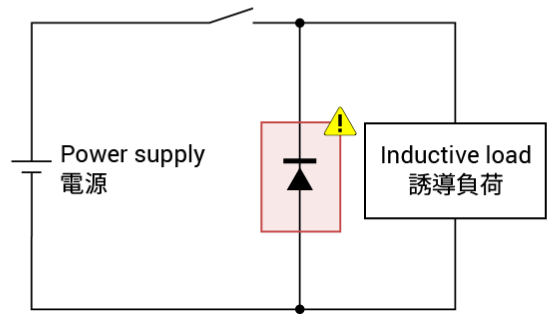
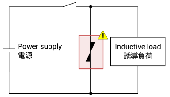
Consider a Contact Protection Circuit
Even if a constant current is set within the power rating, sometimes an inrush current tens of times larger than the rated current can occur with a capacitive or inductive load, or a starting current load, exceeding the absolute maximum rating.
As a countermeasure, please consider adding a contact protection circuit.
Here are some examples.
| Protection circuit |
|
|---|---|
| Constants |
R: Several tens of ohms. C: 0.1µF. |
| Notes | Use when arc-breaking capability between contacts is a concern. |
| Protection circuit |
|
|---|---|
| Constants |
R: Inductive load resistance value. C: 0.1µF. |
| Notes | This CR circuit is recommended as a protection circuit over the example above. |
| Protection circuit |
|
|---|---|
| Constants | Use a diode with a reverse breakdown voltage that is 10 times the circuit voltage and a forward current at least as large as the load current. |
| Notes | If the release time is too long, adding a Zener diode helps. |
| Protection circuit |
|
|---|---|
| Constants | The cutoff voltage of the varistor should be at least 1.5 times the supply voltage. The energy rating should be at least 1J. |
| Notes |
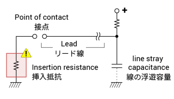
| Protection circuit |
|
|---|---|
| Constants |
With long wiring, inrush current may occur due to stray capacitance. Insert a limiting resistor of 10-50Ω. |
| Notes | The same is required to cope with additional capacitance in ESD protection circuits. |
* Because adding a contact protection circuit extends the release time, you will want to pay attention to the operating time.
- Checking the Specifications
-
Avoid Operating Body Overpush
Excessive pushing can cause faults
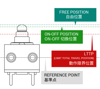
The diagram above shows the names of different positions in a detector switch.
We will refer to the diagram to explain considerations in push design.
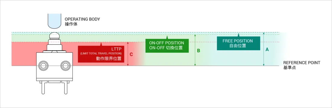
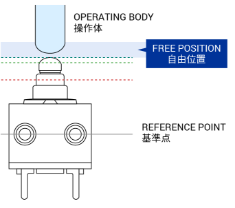
Free position:
Position the operating body at a distance further than A when the switch is off
If the switch is constantly pushed by the operating body, in a state of pre-tension, it may not accurately detect on and off.
To avoid switch pre-tension, set a free position at a distance further than the free position indicated by A.
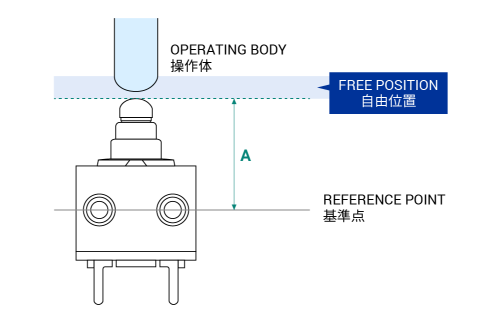
Determination of free position: Position at a distance further than A
* Make sure the switch has no pre-tension in free position.
Full travel distance:
Position the operating body at the midway point between B and C when the switch is on
When the switch is on, the operating body needs to be positioned between the on-off switching position (B) and the limit total travel position (LTTP)(C).
Set the depressed position, when the switch is on, to a position within the red area in the diagram below.
(For convenience, here we will call it the optimum position)
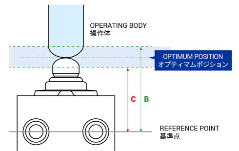
Determination of optimum position: Optimum position is between B and C. Use the midway point. (B+C)/2
Tolerances of B (on-off switching position) and C (LTTP) dimensions must also be taken into account.
A depressed position deeper than the LTTP (C) can cause faults.
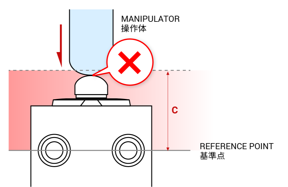
Set full travel to a distance further from the reference line than C.
Tolerance between detector switch and target equipment must be considered when determining an optimal design.
Example: SPVQ810102
ON-OFF POSITION: 7.1mm
LTTP(LIMIT TOTAL TRAVEL POSITION):5.4mm
Position at a distance further than 7.6mm
Caution: Detailed design should take into consideration tolerance of the detector switch, tolerance in installation, and tolerance of push distance.
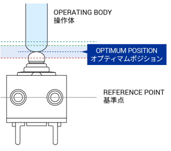
(5.4+7.1)/2=6.15mm
- Checking the Specifications
-
The Right Way to Design Assembly Tools
Assembly Trouble Reason 1: Switch Mounting Plate Design
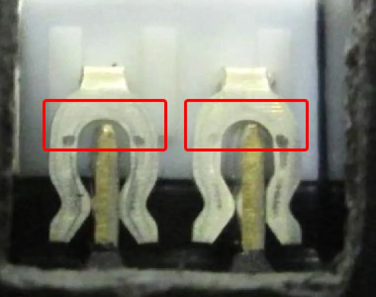
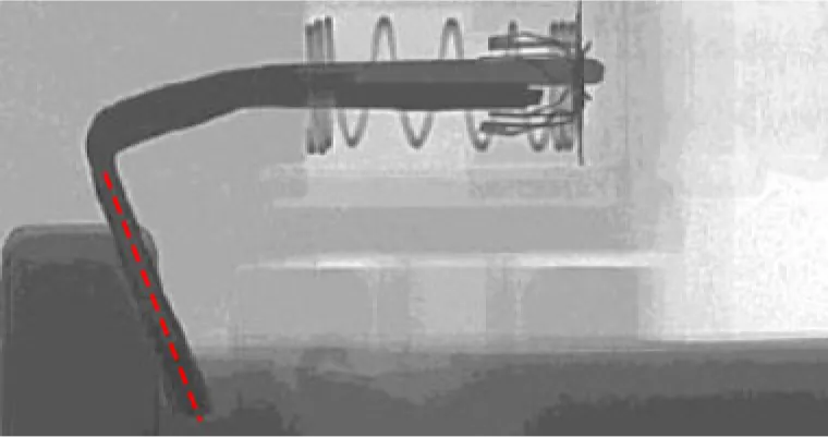
If the switch mounting plate is not designed right, terminals may break or deform during press-fitting, leading to faults.
Design errors relating to terminal length on switch mounting plates can result in contact between plate terminals and switch fork terminals during assembly.
Deformation of switch fork terminals may also occur as they are pushed upward.
Fork terminal deformation affects the contact mechanism inside the switch, potentially causing faults.
Example of terminal deformation due to mismatched switch mounting plate
Take into consideration the tolerance of different parts in design to ensure switch mounting plate terminal ends do not touch switch fork terminals.
To assist design, switch mounting plate 3D data is available on our website.
Please use it as a design reference to prevent terminal faults during press-fitting.
Assembly Trouble Reason 2: Switch Press-fitting
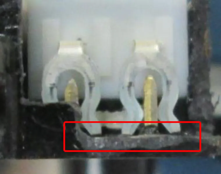
Press-fitting a switch that is tilted may lead to terminal deformation or faults
Example of switch fork terminal deformation
Press-fitting a switch onto a switch mounting plate (PLATE below) with the switch tilted results in deformation of switch fork terminals as the fork terminals do not mate well with the switch mounting plate.
Fork terminal deformation affects the contact mechanism inside the switch, potentially causing faults.
When mounting a switch, take care with the mating of the mounting plate and the switch fork terminals to prevent deformation.
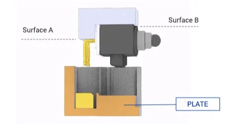
Consider Using an Assembly Jig
When attaching the switch to the affixing part (PLATE above), both the switch body (Surface B) and terminals (Surface A) need to be pushed.
Use of a tool is recommended as making a tool allows easy mounting by pushing on the body and terminals.
To assist design, 3D data for the L-shaped attachment tool is available on our website.
Please use it as a reference when designing tools.
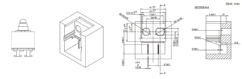
Conceptual diagram of L-shaped attachment tool (example: SPVQ811006)
- Checking the Specifications
-